Jet Nozzles an Essential Part of HDD/Drilling Tooling
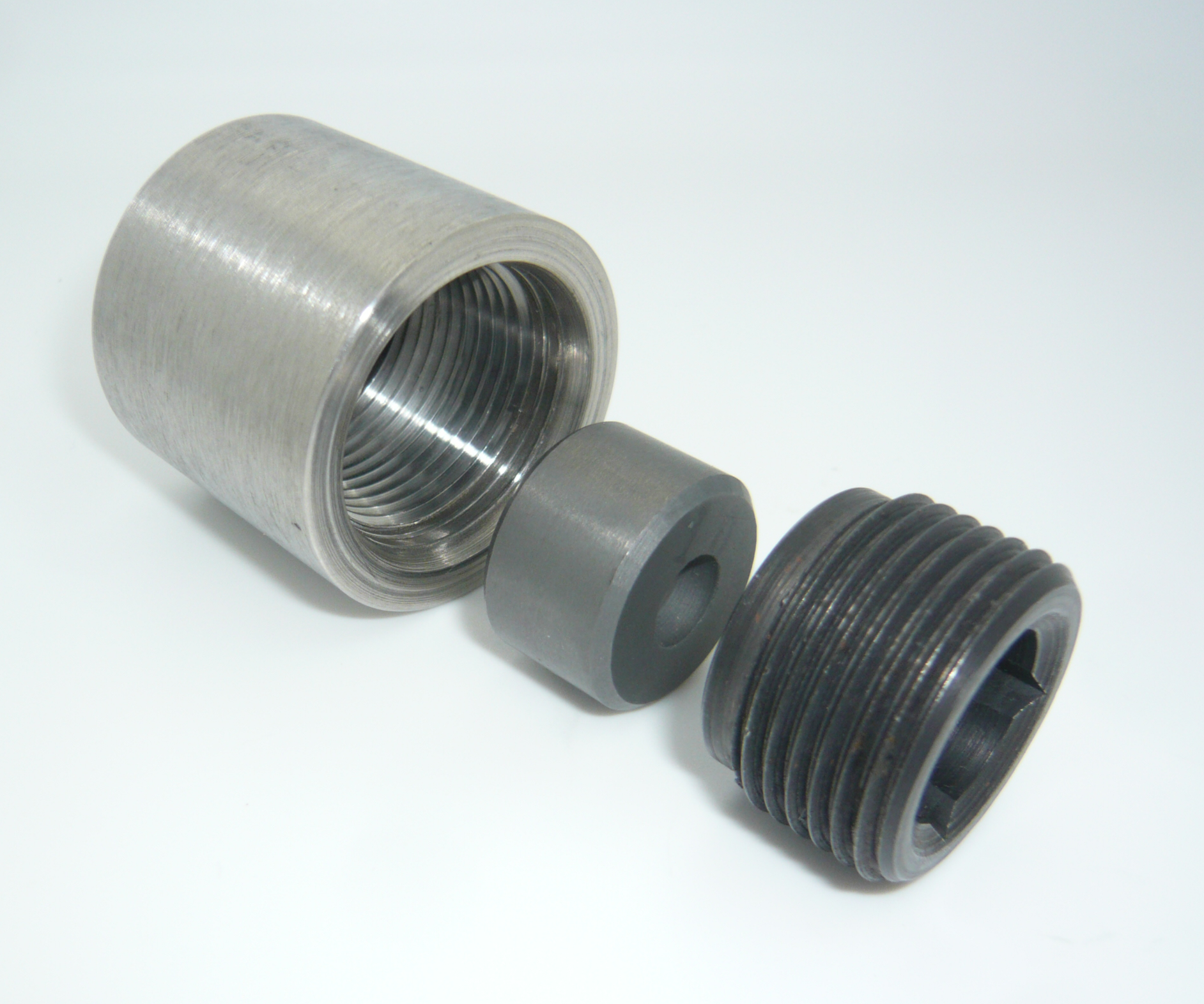
Series 65 Jet Nozzle High-pressure carbide jet nozzle assembly (SS)
Shortly after the development and introduction of HDD in early 1970 it became the quickly became clear the importance of hole opener design and the use and placement of high pressure jet nozzles.
It is sometimes difficult for those entering the HDD industry today to fully appreciate the failures, and subsequent successes that were part of the evolutionary process that have evolved into hole opening methods and procedures commonly used in the HDD industry today. Whereas in-hole hydraulics and hole cleaning practices were well know in the Oil & Gas sector it proved to be far more difficult to carry cuttings out of a shallow surface to surface borehole then a deep vertical well. It was quickly understood that the same procedures and practices did not always apply to cutting and moving large volumes of solids horizontally through a (relatively shallow) borehole, to the surface as required by HDD. Essentially vertical Oil & Gas bore holes relied on lifting cutting (solids) vertically (or near vertical) to the surface in a relatively small diameter column of drilling mud. With the proper drilling
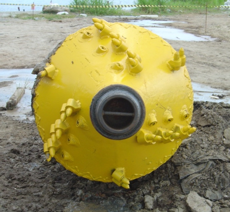
Jet Nozzle Assemblies used in HDD, barrel reamer
medium, viscosity, and flow rate, solids were entrained in the slurry and lifted to the surface through [1]laminar flow. A common practice in Oil & Gas drilling was (and is today) to perform what is referred to as pumping “bottoms up”, the continuous circulation of drilling fluid, lifting the cutting from the bottom of the hole to the surface before the pumps are shut down for any extended periods of time. In simplified terms, cuttings are being raised in a fluid conveyor as they move along with the flow of bentonite to the surface. Removing cuttings from a HDD borehole can be far more complex when the cuttings (solids) are not entrained in a vertical column thousands of feet in depth. The vertical distance that solids can settle before they reach the bottom of the hole and become stagnant is the diameter of the borehole, a distance that is measured in inches not thousands of feet. Solids that settle to the bottom of the borehole are far more difficult to re-suspended and move out of the borehole than those that are entrained in the bentonite slurry. A very high percentage of pipe pull back failures are associated with solids in the borehole, most of which are cuttings that have settled out of the bentonite slurry. The rate in which the cuttings settle (slip) are based on two primary factors, the viscosity of the bentonite slurry in which they are entrained, and the size and weight

(mass) of the cuttings. Bentonite that is to viscous requires too much pressure to keep it moving along the column especially when the column becomes static when the pumps are shut down b
etween joints. When in-hole pressures exceed a certain threshold the formation fractures and returns are lost. Too light of viscous and the cuttings will quickly settle to the bottom of the borehole and becomes stagnant. With the above said, bentonite viscosity has a relatively narrow range in which it can (or should) be adjusted, making the size of the cuttings (solids) an essential consideration.
The size of the cuttings can be affected by many factors e.g. penetration rate, hole opener design and high pressure jet nozzle placement.
- The penetration rate in which hole openers and back reamer’s that are drawn through the hole can easily produce too large of cuttings. Excessive rates will gouging large pieces of formation which ether fall directly behind the hole opener or slip and settle very quickly with no chance of being entrained in the slurry and carried to the surface.
- Hole opener designs can also be critical based on the type of formation being cut. Too aggressive of a hole opener in soft formations can too often leave only a perception of success to those operating the tools at the surface. An example of this is using a fly cutters back reamer in a softer clay formation. By essence of its design, it is easy for an operator without discipline of experience to advance a fly cutter too fast through clay, thus shaving large slivers of clay that fall directly through the blades, settling at the bottom of the borehole as the hole opener continues to advance.
- High pressure jet nozzle placement is also critical. Ideally the nozzles are positioned directly ahead of the mechanical cutting tooth. Proper positioning of the nozzle has two primary benefits, continuous cleaning of the cutting surface, and shearing of the cuttings. A properly position nozzle will continually blast cuttings off and away from the cutting surface so to prevent this cutting surface from becoming “loaded up” diminishing the effectiveness of cutting edge, slowing down production as the rate of penetration (ROP) diminishes. In addition to unloading the cutting edge, the nozzle should shear the formation as it is cut, breaking it down into small particles so that it can be carried effectively out of the borehole without settling in the borehole.
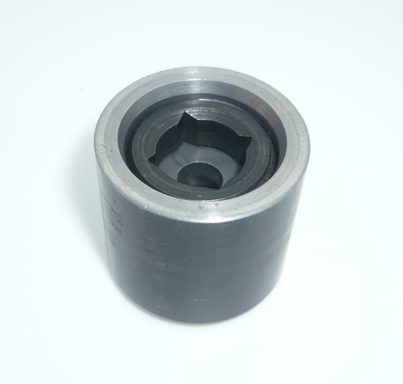
High-pressure carbide jet nozzle assembly (A-513 alloy)
As part of our ongoing commitment to design drilling solutions for the HDD and vertical drilling industry, we have developed and are offering a nozzle assembly that offers a standardized solution to most in hole tooling requirements. The series 65 assemblies are ideally sized and suited for most drilling applications, allowing contractors a standardized nozzle solution for all of your high pressure jet nozzle needs. Nozzle sockets can be mounted flush or counter-bore (flush mount) into drilling tools allowing for serviceability of these tools having a wide selection of nozzle variations. Not only are these assemblies a central part of building in-hole tools e.g. hole-openers, fly-cutters, barrel reamer’s, hole cleaning swabs and jet bits, etc. they are also considered essential for any HDD contractors to have on location for any type of high pressure applications including but not limited mud tank jet guns, mud pit agitation (breaking up solids), wash down tools, etc.
Click here for more information on the Jet Nozzle assemblies used in these hole-openers
[1] laminar flow (lām’ə-nər) Smooth, orderly movement of a fluid, in which there is no turbulence, and any given sub current moves more or less in parallel with any other nearby sub current. Laminar flow is common in viscous fluids, especially those moving at low velocities.
For more on laminar flow